
TL;DR:
- Effective fire suppression system design begins with hazard assessment to classify fire risks based on occupancy and materials.
- Proper sizing and layout involve calculating protected volume, selecting appropriate agents, and coordinating with architectural and mechanical systems early in the process.
Fire suppression system design is the engineering process of selecting, sizing, and integrating detection, control, suppression agents, and delivery hardware to neutralize specific fire hazards in a defined space. For engineers and safety professionals working in industrial and commercial facilities, knowing how to design suppression systems means understanding four core components: the detection network, the control panel, the suppression agent, and the nozzle or delivery array. Standards from NFPA and UL govern every decision, from agent concentration to discharge timing. This guide walks through each design phase in the order you will actually execute it.
How to design suppression systems: starting with hazard assessment
Hazard assessment is the foundation of every suppression system design decision. Before you select an agent or size a pipe, you must classify the fire risk by occupancy type and the materials present. A data center storing server racks presents a Class C electrical hazard. A commercial kitchen generates Class K grease fires. A paint storage room carries a Class B flammable liquid risk. Each classification drives a different system type, agent chemistry, and discharge strategy.
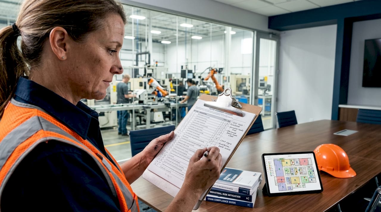
Beyond hazard class, you need to evaluate the physical characteristics of the protected space. Room volume, ceiling height, and enclosure integrity all affect how much agent you need and whether it will stay in the space long enough to suppress the fire. Effective fire protection design requires early multidisciplinary coordination with architectural, mechanical, and IT systems to prevent conflicts and optimize safety outcomes.
For clean-agent systems protecting enclosed spaces, enclosure integrity is not optional. Door fan testing must be included early in the engineering package to identify and remediate leakage paths before installation. This test pressurizes the room and measures air loss to predict whether the space can hold the design concentration for the required 10-minute retention period.
Pro Tip: Schedule the door fan test during the design phase, not after installation. Discovering a leaky cable penetration or an unsealed HVAC damper after the suppression hardware is in place costs significantly more to fix.
Ventilation paths deserve special attention in industrial settings. Active HVAC systems can exhaust agent out of the protected zone within seconds of discharge. Your design must account for automatic damper closure or HVAC shutdown as part of the system’s control narrative.
What suppression agent and system type should you choose?
Agent selection is where fire safety system design becomes highly specific to the hazard. The four primary categories are inert gas systems, clean-agent systems, wet chemical systems, and water-based sprinkler systems. Each has distinct storage, discharge, and residue characteristics that determine where it belongs.
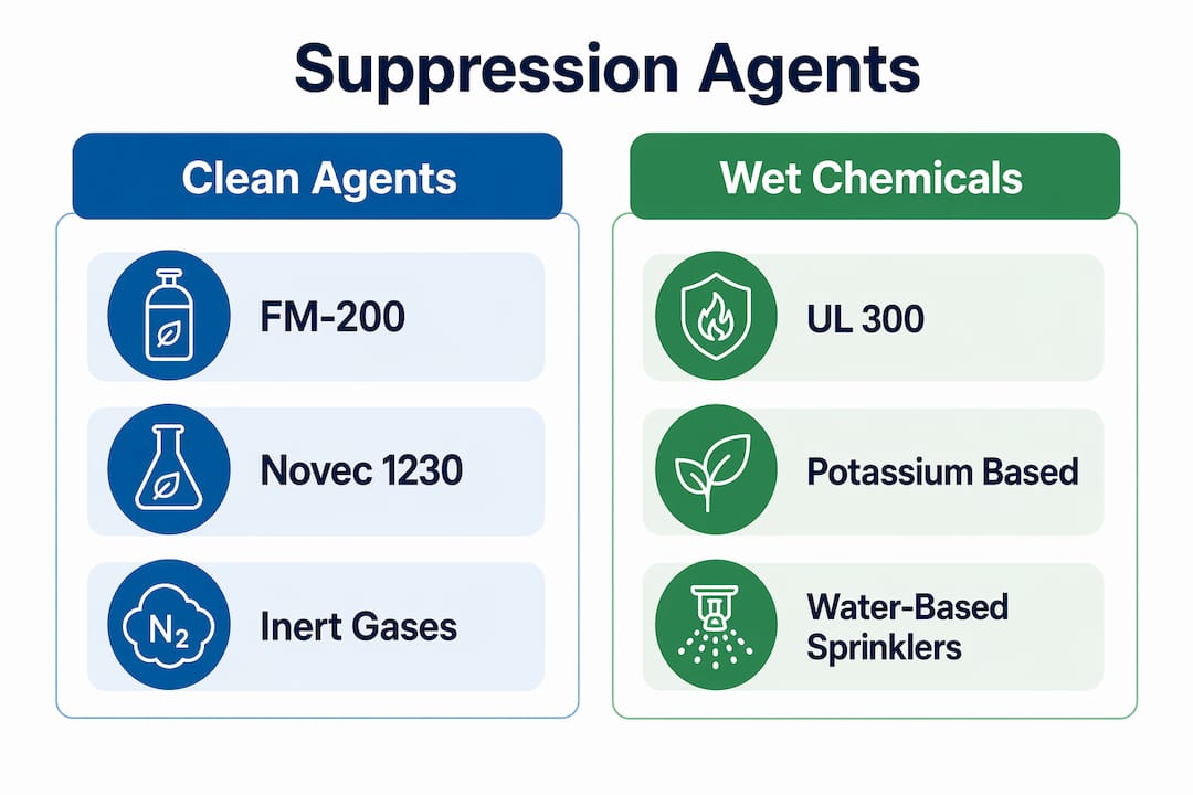
Inert gas systems, such as IG-541 (Inergen) and IG-55, reduce oxygen concentration to a level that cannot sustain combustion while remaining safe for occupied spaces. Clean agents like FM-200 (HFC-227ea) and Novec 1230 (FK-5-1-12) extinguish fire through heat absorption and chemical interference. Gas suppression design requires accurate hazard assessment, space evaluation, agent selection, system sizing, and compliance with NFPA 2001 and ISO 14520 standards. Novec 1230 carries a global warming potential near zero, making it the preferred choice where environmental compliance is a priority.
| System type | Best application | Key standard | Residue |
|---|---|---|---|
| FM-200 / Novec 1230 | Data centers, telecom rooms | NFPA 2001 | None |
| Inert gas (IG-541, IG-55) | Occupied spaces, archives | NFPA 2001 / ISO 14520 | None |
| UL 300 wet chemical | Commercial kitchen hoods | UL 300 | Saponification residue |
| Wet pipe sprinkler | General commercial / industrial | NFPA 13 | Water damage |
For commercial kitchens, UL 300 is the governing standard, not a preference. UL 300 systems discharge potassium-based wet chemical agents that extinguish fires rapidly and simultaneously cut fuel and electrical power to prevent re-ignition. Discharge completes within 30 to 60 seconds, with integrated interlocks shutting off gas and power to cooking appliances. This simultaneous action is what separates a UL 300 system from older dry chemical systems that left re-ignition risk unaddressed.
Pro Tip: When selecting suppression systems for a mixed-use industrial facility, map each zone to its hazard class before choosing a single system type. A warehouse with a server room and a commercial kitchen may require three different suppression technologies under one roof.
Water-based sprinkler systems remain the most widely deployed suppression technology in commercial and industrial buildings. They are cost-effective, well-understood, and governed by NFPA 13. Their limitation is water damage to sensitive equipment, which makes them unsuitable for data centers or archival storage without a pre-action configuration.
How to size and lay out suppression systems effectively
Sizing a suppression system is a calculation-driven process, and errors here directly cause suppression failure. The steps below apply to gaseous systems; water-based systems follow a parallel hydraulic calculation process.
- Calculate protected volume. Measure the net volume of the enclosure, accounting for fixed obstructions like server racks or machinery. Subtract non-communicating sub-volumes.
- Determine design concentration. NFPA 2001 specifies minimum design concentrations for each agent. FM-200 requires 7% by volume for Class A and B hazards. Add a safety margin of 20 to 30% to account for leakage.
- Calculate agent mass. Use the agent-specific formula from NFPA 2001 or ISO 14520, factoring in room temperature and altitude. Higher altitudes reduce agent vapor density and require more agent by mass.
- Size the storage containers. Select cylinder sizes and quantities that deliver the calculated agent mass within the discharge time limit, typically 10 seconds for clean agents per NFPA 2001.
- Design the nozzle layout. Place nozzles to achieve even agent distribution throughout the protected volume. Avoid dead zones behind large obstructions. Manufacturer flow charts specify nozzle coverage areas and orifice sizes.
- Design the pipe network. Size pipes to deliver the required flow rate at each nozzle simultaneously. Pressure drop calculations must confirm that the last nozzle in the network receives adequate flow.
| Design parameter | Typical value | Governing standard |
|---|---|---|
| FM-200 design concentration | 7% by volume (Class A/B) | NFPA 2001 |
| Agent retention hold time | 10 minutes minimum | NFPA 2001 |
| Clean agent discharge time | 10 seconds or less | NFPA 2001 |
| Sprinkler hydraulic residual pressure | Varies by hazard class | NFPA 13 |
For water-based systems, hydraulic calculations determine minimum flow and pressure requirements, ensuring system effectiveness. This stepwise process calculates pipe sizes, minimum flow at the most hydraulically remote sprinkler, and pressure adjustments at each node. Software tools like HydraCalc or SprinkCALC accelerate this work, but the engineer must verify inputs and outputs against NFPA 13 tables.
Coordinate nozzle and pipe routing with the architectural and mechanical drawings early. Conflicts with HVAC ducts, structural beams, or electrical conduit discovered during installation add cost and delay. Early-stage collaboration between fire suppression designers and builders prevents the most common and expensive rework scenarios.
How to ensure compliance, testing, and maintenance after design
A correctly designed system that is never tested or maintained will fail when it matters most. Post-design compliance work falls into three categories: pre-commissioning verification, acceptance testing, and ongoing maintenance.
Before commissioning, verify the following:
- Detection devices and the control panel are integrated and communicate correctly per NFPA 72.
- All penetrations through the enclosure boundary are sealed and documented.
- Agent containers are filled to the specified weight and pressure.
- Abort switches, manual release stations, and audible/visual warning devices are installed and functional.
- Fuel and electrical interlocks for kitchen systems are wired and tested per the control narrative.
NFPA 2001 requires enclosure integrity testing to verify agent retention, as leakage leads to suppression failure even if the system discharges correctly. This test must be repeated after any modification to the enclosure, including new cable penetrations or HVAC changes.
Ongoing maintenance is not optional. NFPA 2001 mandates monthly visual inspections, semi-annual container weighing, and five-year hydrostatic testing of cylinders. Skipping semi-annual checks is the most common cause of discovering an under-filled system during an actual fire event.
Semi-annual container checks confirm that agent quantity has not dropped below the minimum design concentration. Slow leaks from valve seats or cylinder threads can reduce agent mass by 5 to 10% per year without triggering any alarm. A system that discharges at 85% of design concentration may not achieve suppression in a worst-case fire scenario.
Engage your authority having jurisdiction (AHJ) and insurance carrier early in the design process. Early design review involving insurance and compliance agencies reduces costly redesigns by confirming system ratings, water supply adequacy, and plan completeness before construction begins.
Common mistakes in suppression system design and how to avoid them
Even experienced engineers make predictable errors in fire suppression design. Recognizing these patterns before they reach the field saves time, money, and lives.
- Ignoring enclosure leakage. Designing a clean-agent system without a door fan test is the single most common cause of suppression failure. Undetected leaks through cable trays, conduit sleeves, or raised floor voids allow agent to escape within seconds of discharge.
- Delaying interdisciplinary coordination. Fire suppression drawings issued late in the design process conflict with HVAC, structural, and electrical systems. Multidisciplinary coordination must begin at schematic design, not during construction documents.
- Misunderstanding kitchen discharge timing. UL 300 systems require discharge within 30 to 60 seconds with simultaneous fuel and power interlocks. Designers who treat kitchen suppression as a simple nozzle-and-agent problem miss the integrated control narrative requirement entirely.
- Underestimating maintenance complexity. A suppression system with 12 cylinders, 40 nozzles, and integrated HVAC interlocks requires a documented maintenance program, not an annual visual check.
- Submitting incomplete plans. Early plan submission with detailed specs and hydraulic calculations leads to better project outcomes. Incomplete submittals trigger review cycles that delay permits and push installation schedules.
Pro Tip: Engage your insurance carrier and the AHJ during the design development phase, not at permit submission. Both parties can identify compliance gaps before they become change orders.
Key takeaways
Effective suppression system design requires hazard classification, agent selection, accurate sizing calculations, and rigorous post-installation testing to achieve reliable fire protection.
| Point | Details |
|---|---|
| Hazard assessment first | Classify fire risk by occupancy and materials before selecting any system type or agent. |
| Agent selection drives system type | FM-200, Novec 1230, inert gas, UL 300 wet chemical, and sprinklers each serve distinct hazard profiles. |
| Sizing requires calculation | Use NFPA 2001 formulas for agent mass and NFPA 13 hydraulic methods for water-based systems. |
| Enclosure integrity is a gating factor | Door fan testing must confirm 10-minute agent retention before system acceptance. |
| Early review prevents rework | Engage the AHJ and insurance carrier during design development to avoid costly late-stage changes. |
What field experience teaches about suppression system design
After years of working on suppression projects across data centers, commercial kitchens, and industrial facilities in Houston, the pattern I see most often is this: engineers treat suppression design as a product selection exercise rather than an integrated engineering problem. They pick an agent, size the cylinders, and hand off the drawings. The enclosure integrity work gets deferred. The HVAC coordination happens late. The kitchen control narrative gets simplified. Then the system fails its acceptance test, and everyone is surprised.
The most reliable systems I have seen come from projects where the suppression designer was in the room during schematic design, not brought in at construction documents. That early seat at the table means the enclosure is designed to hold agent, the HVAC dampers are specified correctly from the start, and the kitchen hood layout accounts for nozzle coverage before the ductwork is fabricated.
Clean-agent systems in particular demand respect for physics. The agent is heavier than air, and any floor penetration or raised access floor void becomes a drain. I have seen correctly sized FM-200 systems fail their door fan tests because a single unsealed conduit sleeve allowed the agent to drain out within four minutes. The fix was a $40 firestop plug. The delay cost three weeks.
My advice: treat the suppression system workflow as a discipline that runs parallel to architecture and mechanical from day one. The code minimum is not the design goal. The design goal is a system that works on the worst day of the building’s life.
— Reliable-fire-protection
How Reliable Fire Protection supports your suppression system needs
Reliable Fire Protection provides engineering consultation, system design, installation, and ongoing maintenance for fire suppression systems across Houston’s industrial and commercial sectors. Whether you are designing a clean-agent system for a data center, a UL 300 kitchen hood system for a restaurant group, or a wet pipe sprinkler network for a warehouse, the team brings certified expertise and local code knowledge to every project.
Understanding how fire alarm systems work is the first step toward integrating detection with your suppression design. Reliable Fire Protection handles that integration from initial design review through acceptance testing and scheduled system maintenance, so your facility meets NFPA and UL standards without gaps. Contact the team for a free consultation and project review.
FAQ
What is the first step in designing a fire suppression system?
Hazard assessment is the first step. Classify the fire risk by occupancy type and materials present before selecting any agent or system type.
How do you size a clean-agent suppression system?
Calculate the protected volume, determine the required design concentration per NFPA 2001, then compute agent mass using the agent-specific formula. Add a 20 to 30% safety margin for enclosure leakage.
What does a door fan test verify in suppression system design?
A door fan test measures enclosure leakage to confirm the space can retain the design agent concentration for at least 10 minutes, as required by NFPA 2001.
When is a UL 300 system required instead of a clean-agent system?
UL 300 is required for commercial kitchen hood protection. It uses potassium-based wet chemical agents and integrates fuel and electrical interlocks, which clean-agent systems do not provide for grease fire hazards.
How often must suppression system containers be inspected?
NFPA 2001 requires monthly visual inspections and semi-annual container weighing to confirm agent quantity has not dropped below the minimum design concentration.